I had a number of responses on my locostusa.com build thread about my dashboard, mostly praise and inquiries as to how specifically I’ve created what I’ve got so far. To answer those questions and provide a resource for those in the future who may be interested in doing a similar dashboard, I’ll try to document my dash fabrication here. I will update this post accordingly as my dashboard progresses to completion.
Background: What and why?
 The Caterham 7 is the direct descendant of Colin Chapman’s original Lotus 7. Caterham Cars was a major dealer of 7′s in the 1960′s, and when Lotus announced its intention to discontinue the 7, Caterham bought the rights to continue manufacturing the 7 from Chapman. The rest, as they say, is history. Caterham now produces some of the fastest machines on four wheels in the world, despite their most expensive car coming in at just over $60k. The referenced vehicle, the Superlight R500, holds the rank of 5th fastest on top gear’s powerboard at the time of this writing (which places it ahead of the bugatti veyron, the ferrari enzo, and many other supercars).
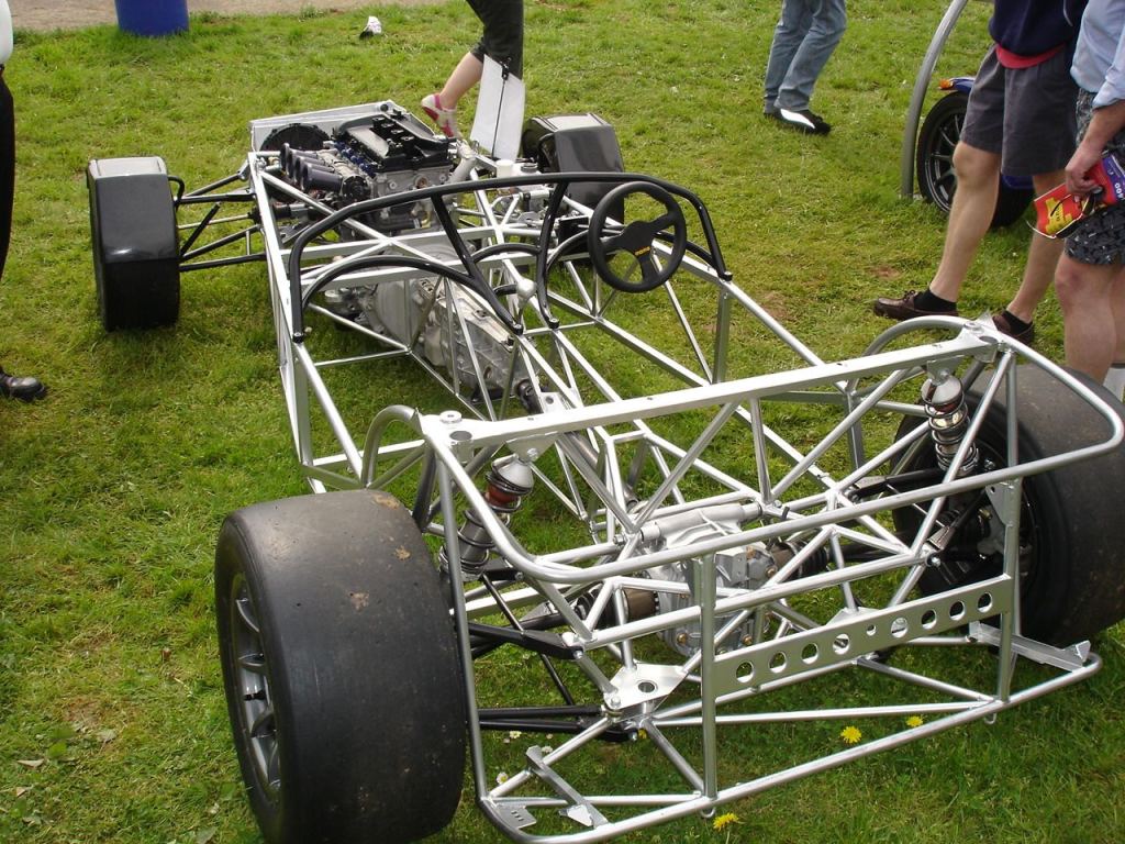
 Anyways, long story short, Caterham 7′s are *extremely *nice, in every way imaginable. Inside and out, they are very well done, and are some of the best looking 7′s out there, in my humble opinion. One Caterham 7 in particular has an interior that is totally kickass, the CSR. The dashboard pictured above is from one. The dash structure and the frame are apparently seamless and the dash structure is totally exposed, giving it a skeletal yet sexy look. In between the spaces created by the dash frame are three panels, a cubby hole, the shifter, a few gauges and a couple of heater vents. My goal for my locost is to emulate this look as closely as possible; I want my 7 to look factory-built.. I don’t want people who come up to me on the street to be able to guess that I built it in my garage from scratch.
The Good Stuff: How
 Lets get down to business. I’m assuming that you already know roughly how tall and wide you want your dash to be. Mine is about 12″ tall at the tallest point, and it extends the width of my frame (42″). Secondly, you need to decide how you want your dash attached to the frame. My own dash frame is welded directly onto the frame of the car. This ought to increase the torsional rigidity of the frame a decent amount, since the open passenger compartment is one of the main weaknesses in the 7′s frame. I’m planning on making a dash cover out of aluminum with a light-weight steel frame riveted to it, which will in turn bolt to the frame of the car in order to fasten it in place.
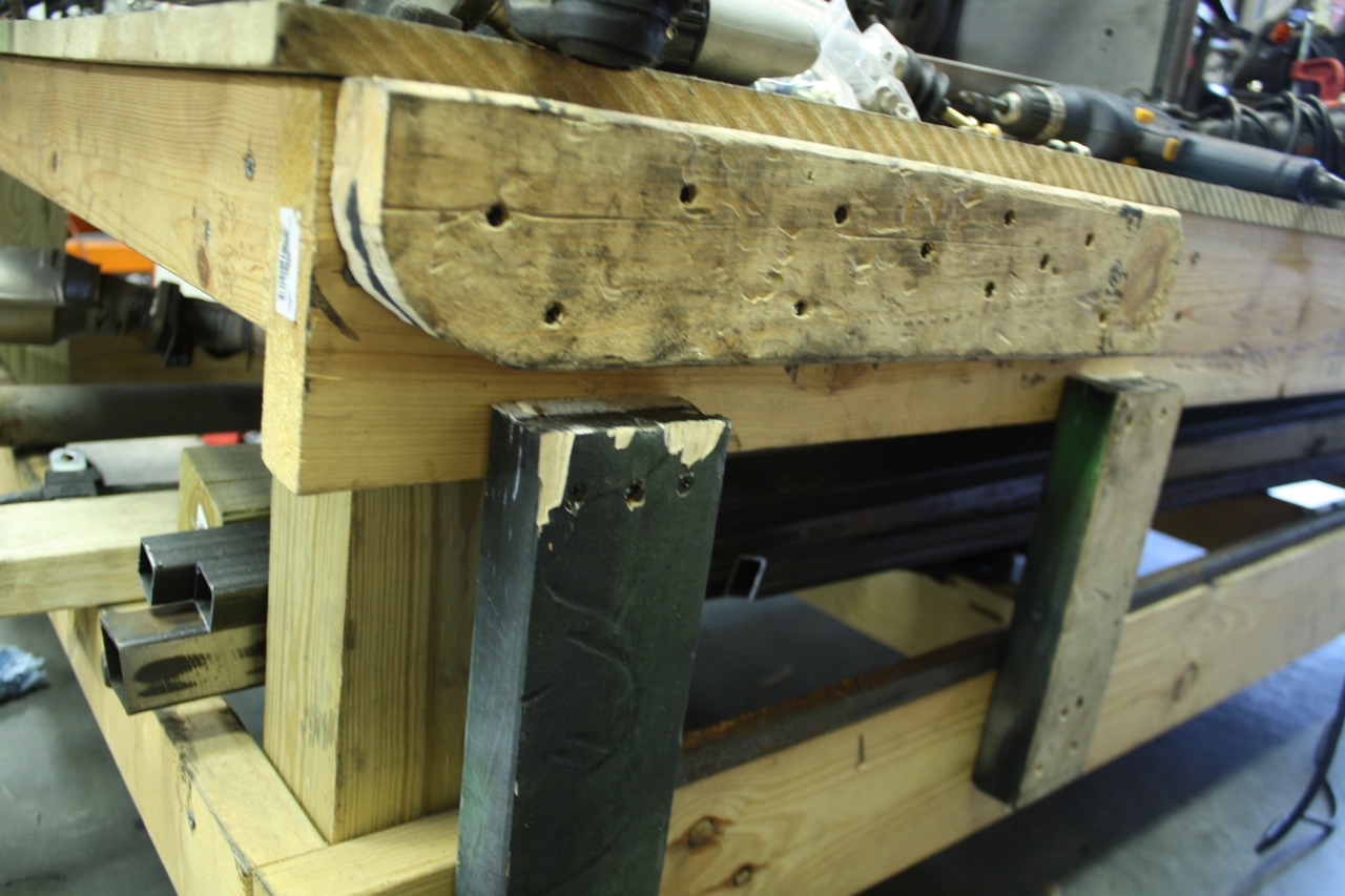
 First of all you have to have a way to bend your tubes. Mine is less than sophisticated but surprisingly effective. I took a 2×4 that I had laying around that’s a couple feet long, and with my band saw I rounded one of the corners to a fairly large-radius curve. I took that one and 2 more 2×4′s and screwed them to the side of my build table in such a way that I can put a tube in between them.
 One other thing that I found helpful before I actually started bending real tubes was mocking up the dashboard with tig welding rod. If you don’t have any on hand, coat hangers will work just as well. I started out with the top rail, then I did the tubes that go from the transmission tunnel to the top rail, then the round tubes that cross over the passenger compartments, and lastly I did the “tubes” that cross between the two vertical ones.
If you look at the caterham pictures you’ll notice that the upper dash rail is bend in multiple planes. It arches over the car but it also arches away from the driver compartment. I modeled my mockup and my final rail after this.
 In order to begin bending the top rail, I first began with one of the corners. I took one of my 12′ sections of round tubing and hammered it my tube bender, with as much of it hanging out on the bending end as possible. I then grabbed the tube and pulled up, bending the tube.. I bent it to about 70 degrees or so. I then took the tube and compared it against my mock-up (I did this a lot, another reason why a mock-up is useful). Making sure that the bend was how I wanted it, I proceeded to start working on the bends across the top rail. Not counting the corners, my top rail has a total of 4 very slight bends in it… Using the picture of the caterham frame for referenced, I first placed one close-ish to the corner, then I placed one closer to the center of the rail, about where the vertical tube attaches to it. At this point I did the other corner (measuring to approximately where I thought it should be), and after that was done I did the last two bends just like the first two. Finally, to make sure everything was symmetrical, I drew out a 42″ x 12″ rectangle on my build table (sliding the frame back to make room) and positioned the dash rail on it. I measured the angles of the side tubes, distances and lengths, etc, and also checked to see that the vertical tubes were in the same plane (not twisted relative to each other). I kept making adjustments by bending slightly until everything was symmetric to my satisfaction. Finally I chopped off the excess steel from the vertical tubes so that my dash wasn’t 20″ high, and tac welded it to my frame.
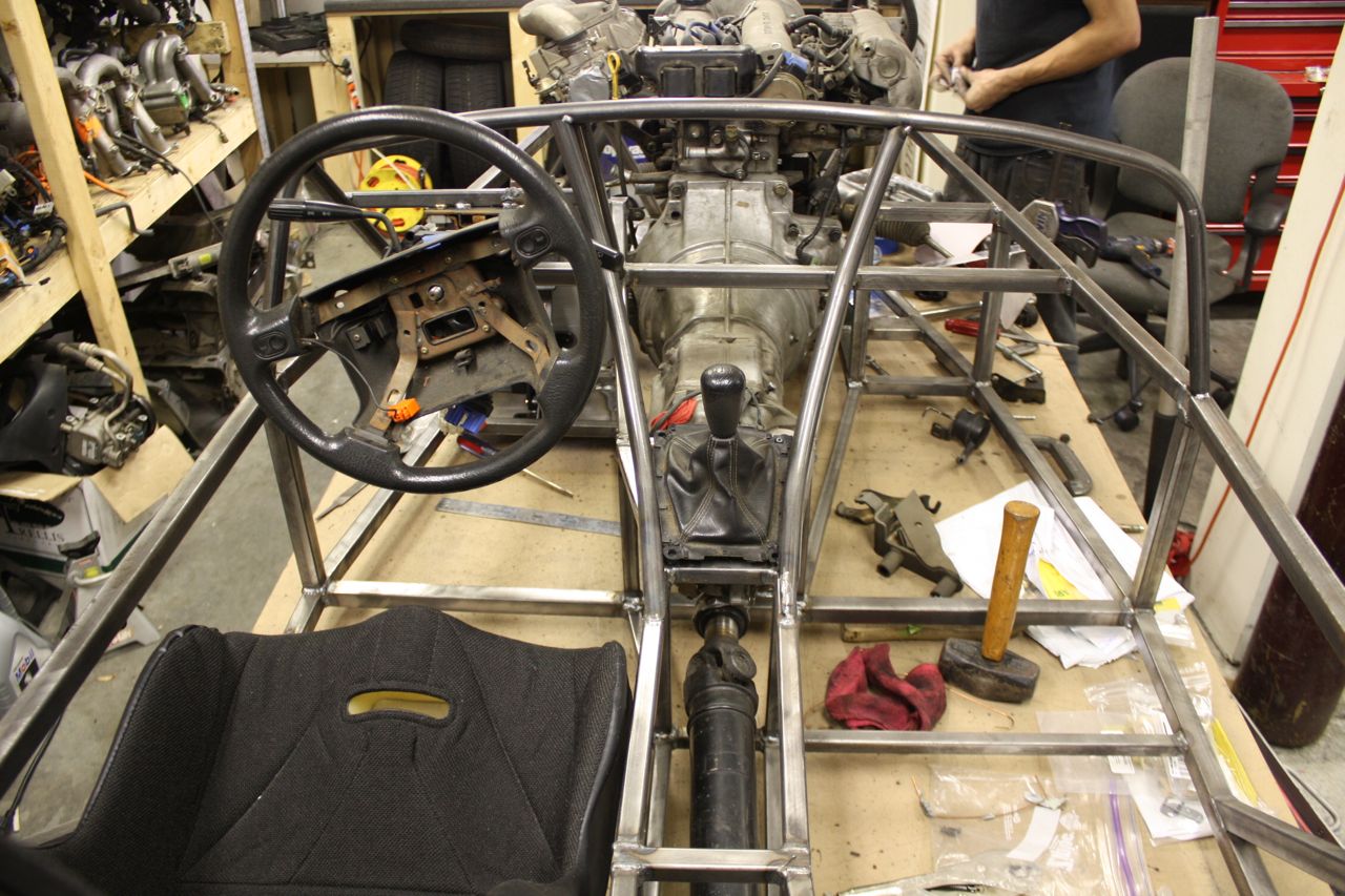
 The next order of business is the tubes that go from the transmission tunnel to the top rail. Mine are actually 3 separate bends each.. They were pretty simple to make with my bender, the main thing was to make sure that I made the bends in the exact same place on the second tube so that they would be symmetric. Note that you have to make sure the tubes extend down past where your shifter is, and also that the inclination of the tubes along the shifter has to be such that you can actually shift into 1st/3rd/5th as well as 2nd/4th/reverse. Here are some more pictures to show what I mean:


To Be Continued…
That’s about all I’ve done so far on my dash. As I said before, I’ll update this post as I make more progress, and of course I’ll include up-to-date pictures as well. The next orders of business are the tubes that go over the passenger compartments, the tubes that go in between the two center tubes, and the actual cover/removable section (this will probably come much later).